Aluminum PCB
| P/N: Q2E18851A0 | Layer Count: 1L | Min Line W/S: 16/8mil |
| Material: Aluminum | Cu Thickness: 1oz | Min PTH: 0.45mm |
| Board Thickness: 1 .0mm | Surface: OSP | Application: LED |
| Soldermask Color: Yellow | Board Size: 289.00mmX265.00mm(20-up) | |
What type of aluminum baord can Victory make?
Single-sided aluminum board
This aluminum substrate is the most common kind, relatively simple process, and especially widely used.
Double layer aluminum board
The most common is a 2 - or 4-layer subassembly made from conventional FR-4, and bonding this layer to an aluminum substrate with a thermoelectric medium can help dissipate heat, improve rigidity and act as a shield.
Multi-layer aluminum Board
In the high-performance power supply market, multilayer IMSPCB is made of multilayer thermal conductive dielectric. These structures have one or more layers of circuits embedded in the dielectric, with blind holes used as thermal through holes or signal paths.
Products application
Aluminum-backed PCBs are ideal for situations when thermal heat tolerance and dissipation requirements are very high. PCBs clad with aluminum are more effective at directing thermal energy away from printed circuit board components; therefore, they provide better temperature management for PCB designs.
Aluminum-backed designs can be as much as 10 times more efficient than fiberglass-backed designs when it comes to removing thermal energy from circuit board components. The much higher thermal dissipation rate allows higher power and higher density designs to be implemented.
Aluminum-backed PCBs are used more than ever for applications of high power and high thermal heat dissipation. Although they were originally designed for high power switching supply applications, aluminum-backed printed circuit boards have gained popularity in LED applications, including traffic lights, automotive lighting and general lighting.
The use of aluminum designs allows the density of LEDs in the PCB design to be higher and for the mounted LEDs to operate at higher currents while staying within specified temperature tolerances.
Industry information
First of all, let's take a look at the expression form of steel stencil layer on CAM software:
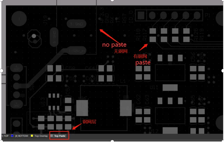
You will find that some devices in the steel stencil layer are steel mesh, some are not steel mesh, we carefully observe that there are steel stencil are patch devices, no steel stencil are plug-ins.
So what causes there to be no steel stencil in the in-line device? Did we miss it when we drew the package? In fact, it is not, we first understand the role of steel mesh, you know why only patch devices have steel mesh.
First of all, our PCB design needs to be produced in the board factory, and then it needs to be fabricated in the patch factory. The welding of the patch device is divided into the welding of the patch device and the welding of the in-line device. The technology used for these two types of devices is different, the surface patch device adopts reflow welding process, while the in-line device adopts wave soldering process
Reflow soldering: refers to the process of melting pre-coated solder paste (solder paste is usually composed of a mixture of tin powder and flux), so that it returns to a flowing liquid state (this process is reflux), so that pre-placed on the solder plate on the device and the solder in full contact to achieve the purpose of welding.
Wave crest welding: usually the welding surface is directly in contact with the solder after melting at high temperature to form a wave crest so as to achieve the purpose of welding.
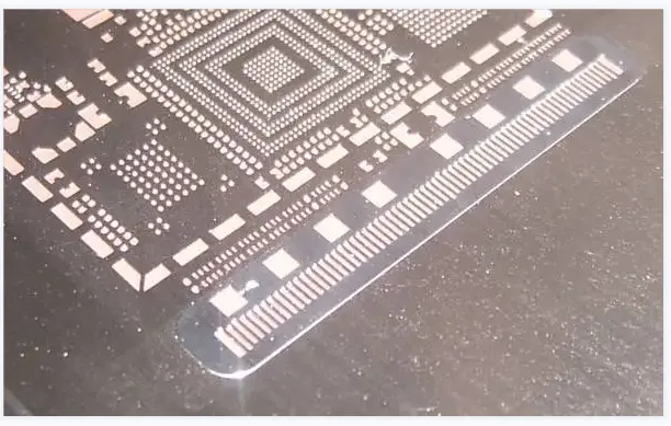
After we understand the above information, we will find that reflow welding is to be coated with solder on the pad in advance, so the solder paste placed on the pad is sure to need tools, our steel stencil layer is used in welding to patch packaging pad solder paste, steel stencil refers to the corresponding position of the steel plate in the patch pad open holes, and then apply solder paste on the steel plate, The solder paste will fall into the pad from the hole, which is the role of our steel mesh, so our steel stencil layer in cam software is only in the patch device, which is why there is no steel stencil plug-in.
Then whether our steel stencil layer and solder resistance layer need to be expanded, in fact, this is not needed, external expansion is mainly for our solder resistance layer, the size of the steel stencil layer is needed and the size of the solder pad, so that we can accurately coated with solder.
What is Aluminum PCB?
Aluminum PCBs, also known as metal core PCBs, are a type of printed circuit board that uses aluminum as the base material instead of the traditional FR4. The primary reason for using aluminum is its excellent thermal conductivity, which helps in dissipating heat more efficiently. This makes aluminum PCBs ideal for high-power applications where heat management is crucial. Unlike FR4 PCBs, aluminum PCBs can handle higher temperatures, reducing the risk of thermal damage to components.
Why Use Aluminum in PCBs?
Aluminum is chosen as the base material for PCBs due to its unique properties. It offers superior thermal conductivity, which is essential for applications that generate significant heat. Additionally, aluminum is lightweight, durable, and cost-effective compared to other metals like copper. These characteristics make aluminum PCBs a preferred choice in industries where heat dissipation and reliability are critical.
How is an Aluminum PCB Structured?
The structure of an aluminum PCB consists of several layers:
- Aluminum Base Layer: Provides mechanical support and heat dissipation.
- Dielectric Layer: Acts as an insulator and bonds the aluminum base to the copper layer.
- Copper Layer: Forms the circuit pattern and conducts electricity.
These layers work together to ensure optimal performance, especially in high-temperature environments.
How Are Aluminum PCBs Manufactured?
The manufacturing process of aluminum PCBs involves several precise steps to ensure high quality and performance. Here’s a step-by-step overview:
- Material Selection: High-quality aluminum, copper, and dielectric materials are chosen based on the application requirements.
- Layer Preparation: The copper layer is etched to create the desired circuit pattern.
- Bonding: The dielectric layer is applied to bond the aluminum base and copper circuit layer.
- Lamination: Layers are pressed together under heat and pressure to ensure a strong bond.
- Drilling and Plating: Holes are drilled for component mounting, and vias are plated to establish electrical connections.
- Final Finishing: A solder mask and surface finish are applied to protect the board and enhance solderability.
How Do Aluminum PCBs Work?
Aluminum PCBs work by leveraging the thermal conductivity of the aluminum base to dissipate heat generated by electronic components. The dielectric layer ensures electrical insulation while allowing heat to transfer efficiently from the copper circuit layer to the aluminum base. This heat dissipation prevents thermal damage to components, making aluminum PCBs ideal for high-power applications such as LED lighting, power converters, and motor controllers.
Where Are Aluminum PCBs Used?
Aluminum PCBs are widely used in industries that require efficient thermal management and high reliability. Some common applications include:
- LED Lighting: Aluminum PCBs are extensively used in LED modules and fixtures due to their ability to handle high heat output.
- Automotive Electronics: Power controllers, headlights, and engine management systems benefit from the durability and thermal performance of aluminum PCBs.
- Power Supplies: Switching power supplies and inverters use aluminum PCBs to manage heat generated by high-power components.
- Industrial Machinery: Motor drives, power converters, and industrial automation systems rely on aluminum PCBs for their robustness and thermal efficiency.
What Are the Advantages of Aluminum PCBs?
Aluminum PCBs offer a range of benefits that make them a preferred choice for many high-performance applications. Key advantages include:
- Superior Heat Dissipation: The aluminum base efficiently transfers heat away from components, preventing overheating and extending the lifespan of the PCB.
- Mechanical Strength: Aluminum is more durable and resistant to mechanical stress compared to traditional FR4 materials, making it suitable for harsh environments.
- Lightweight Properties: Despite its strength, aluminum is lightweight, which is advantageous for portable and compact devices.
- Cost-Effectiveness: Aluminum PCBs reduce the need for additional heat sinks and cooling systems, lowering overall costs in high-power applications.
Why Are Design Considerations Critical for Aluminum PCBs?
Designing aluminum PCBs requires careful consideration of several factors to ensure optimal performance and reliability. Key design considerations include:
- Thermal Conductivity: Selecting materials with high thermal conductivity to maximize heat dissipation.
- Via Design: Properly designing vias to ensure efficient heat transfer and electrical connectivity between layers.
- Component Placement: Strategically placing heat-generating components to optimize thermal management.
- Heat Flow Management: Designing the PCB layout to facilitate smooth heat flow and prevent hot spots.
These considerations are essential for achieving the desired performance in high-power and high-temperature applications.
How Are Aluminum PCBs Tested and Inspected?
Ensuring the quality and reliability of aluminum PCBs involves rigorous testing and inspection. Common methods include:
- Thermal Cycling: Subjecting the PCB to repeated temperature changes to test its durability and thermal performance.
- Electrical Testing: Verifying the continuity and functionality of the circuits to ensure they meet design specifications.
- Visual Inspection: Checking for surface defects, such as soldering errors or misaligned components, using automated optical inspection (AOI) systems.
- X-Ray Inspection: Detecting internal defects, such as voids in vias or layer misalignment, that are not visible to the naked eye.
These testing methods help ensure that aluminum PCBs meet the required standards for quality and reliability.
What Quality Standards Apply to Aluminum PCBs?
Aluminum PCBs must adhere to stringent quality standards to ensure their performance and durability. Key standards include:
- IPC Standards: The IPC-6012 standard specifies the performance and qualification requirements for rigid PCBs, including aluminum PCBs.
- ISO 9001: This international standard ensures that manufacturers follow a quality management system to deliver consistent and reliable products.
- UL Certification: Underwriters Laboratories (UL) certification ensures that the PCBs meet safety and performance criteria for specific applications.
Adhering to these standards is crucial for ensuring the long-term reliability and performance of aluminum PCBs in various industries.
FAQ
Reviews