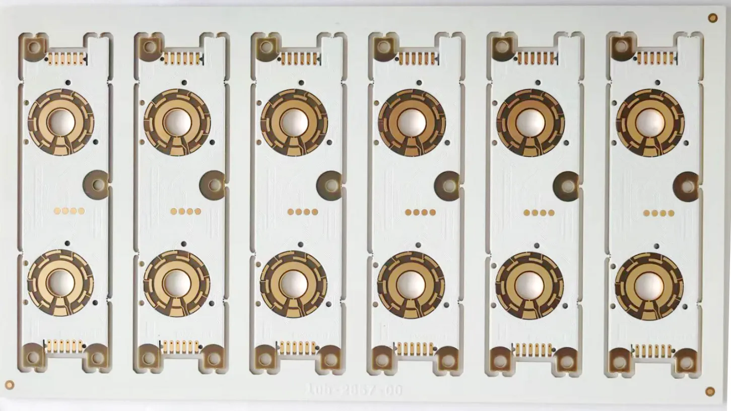
Rogers PCB
| P/N: Q2P06438A0 | Layer Count: 2L | |
| Material:RO4350B. | Cu Thickness: 1oz | |
| Board Thickness: 0. 7mm | Surface: HAL Leadfree | Application:RF |
| Soldermask Color: Green | Board Size: 75mm*130mm | |
Product Features
What is Rogers PCB
Roger PCB refers to printed circuit boards (PCBs) manufactured using Rogers materials. Rogers material is a high-performance, high-frequency circuit board material developed by Rogers Corporation in the United States. This material has the characteristics of low dielectric constant, low loss, high stability, and high temperature resistance, making it suitable for circuit design in high frequency, high-speed, and microwave frequency bands.
Rogers PCB
Rogers: RO4003, RO3003, RO4350, RO5880, etc. With the development of 5G millimeter waves, Rogers has also launched multiple low loss circuit boards suitable for millimeter waves.
Rogers PCB board material ceramic high-frequency board series classification:
- RO3000 series: PTFE circuit materials based on ceramic filling, with models including RO3003, RO3006, RO3010, and RO3035 high-frequency laminates.
- RT6000 series: PTFE circuit material based on ceramic filling, designed for electronic and microwave circuits that require high dielectric constant. The part number include RT6006 with a dielectric constant of 6.15 and RT6010 with a dielectric constant of 10.2.
- TMM series: composite materials based on ceramics, hydrocarbons, and thermosetting polymers, models: TMM3, TMM4, TMM6, TMM10, TMM10i, TMM13i. and so on.
Products application
Rogers is progressing in line with rapid technology development. Its materials serve customer needs for a wide range of industries. Explore the markets we serve and applications of your products.
- Active Safety Device
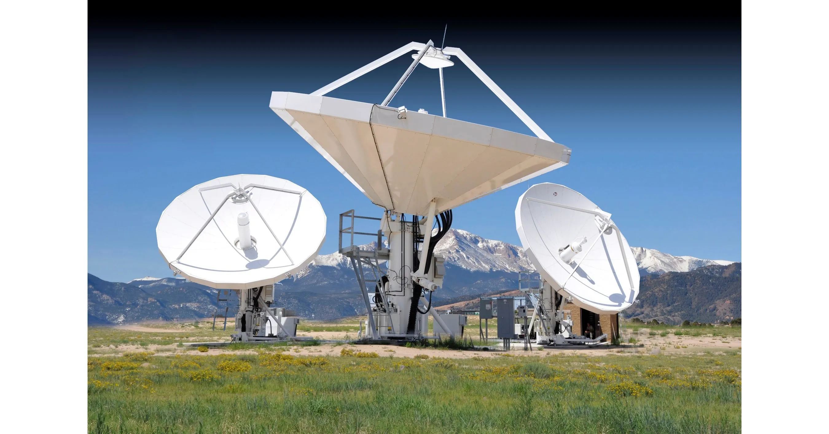
- Antenna System
- Backhaul Radios
- Communication Systems
- Handheld Device Cellular and Wifi Antenna
- Power Amplifiers
- Telematics and Infotainment
Rogers material that we usually manufacture are RO3003, RO3006, RO3010, RO3035, RO3200, RO4000 LoPro, RO4003C, RO4350B, RO4360G2, RO4400 and RO4835.
Industry information

On May 9th, Rogers announced plans to establish a new factory in China to produce curamik ® AMB (active metal brazing) and DBC (direct bonded copper) substrates to meet significant demand growth. The first phase of the expansion is planned to be completed by 2025. Previously, Rogers increased investment and increased curamik for its Eschenbach factory in Germany last year ® The production capacity of the product.
It is worth nothing that Curamik from Rogers Company ® The product series provides first-class metallized ceramic substrates, leading the industry in the fields of power electronics and printed circuit applications. Curamik ® The substrate is made by bonding or brazing pure copper material onto a ceramic substrate, which can carry higher currents, achieve higher voltage insulation performance, and have a wide range of operating temperatures.
What is a Rogers PCB?
A Rogers PCB is a high-performance printed circuit board made with specialized materials from Rogers Corporation, known for their superior electrical properties. Unlike traditional FR4-based PCBs, Rogers PCBs are engineered for high-frequency and RF (radio frequency) applications, offering low dielectric loss and excellent thermal stability. They’re a top choice for industries like telecommunications, aerospace, and automotive, where signal precision and reliability are critical.
What Are the Properties of Rogers PCB Materials?
Rogers PCB materials stand out due to their unique characteristics:
- Low Dielectric Constant: Ensures minimal signal distortion.
- Low Loss Tangent: Reduces energy loss at high frequencies.
- Thermal Stability: Maintains performance across temperature ranges.
- High Conductivity: Supports efficient signal transmission.
These properties make Rogers PCBs ideal for demanding, high-speed electronics.
Why Do Rogers PCBs Outperform Traditional PCBs?
Rogers PCBs offer distinct advantages over standard FR4 boards:
- Signal Integrity: Superior materials reduce signal loss.
- Frequency Range: Excels at GHz frequencies where FR4 fails.
- Heat Management: Better thermal conductivity for stability.
- Durability: Resists environmental stress longer.
These benefits make Rogers PCBs a premium option for advanced applications.
How Does a Rogers PCB Improve Signal Integrity?
Rogers PCBs enhance signal integrity by minimizing distortion and interference. Their low dielectric constant keeps signal speeds consistent, while the low loss tangent reduces attenuation over long distances. Tight manufacturing tolerances and smooth copper surfaces further cut down on noise, ensuring clean, accurate data transmission—vital for RF and microwave circuits.
How Are Rogers PCBs Manufactured?
The manufacturing process for Rogers PCBs is tailored to their high-performance materials:
- Material Prep: Select Rogers laminates like RO4000 or RO3000.
- Circuit Design: Plan precise traces for impedance control.
- Lamination: Bond layers under strict heat and pressure.
- Etching: Form circuits with high-accuracy techniques.
- Testing: Verify electrical and thermal performance.
This process ensures the boards meet exacting standards for high-frequency use.
What Types of Rogers PCBs Exist and Where Are They Used?
Rogers offers various PCB types, each suited to specific needs:
- RO4003C: High-frequency telecom and antennas.
- RO4350B: RF circuits in aerospace and radar.
- RT/duroid 5880: Microwave applications with ultra-low loss.
These variants cater to diverse industries requiring top-tier performance.
Why Are Rogers PCBs Ideal for High-Frequency Applications?
Rogers PCBs shine in high-frequency settings due to their ability to handle rapid signals. Their low dielectric loss preserves signal strength at frequencies above 1 GHz, while stable thermal properties prevent performance drops under heat. This makes them perfect for 5G networks, satellite systems, and other high-speed technologies.
What Features Make Rogers PCBs Stand Out for RF and Microwave Circuits?
Rogers PCBs are tailored for RF and microwave needs with key features:
- Consistent Dielectric: Ensures predictable signal behavior.
- Low Moisture Absorption: Maintains performance in humid conditions.
- Smooth Copper: Reduces signal noise and loss.
These traits deliver reliability in sensitive communication systems.
How Do You Pick the Right Rogers PCB for Your Needs?
Selecting the ideal Rogers PCB involves key considerations:
- Frequency: Match material to your signal range (e.g., RO4350B for 10 GHz).
- Thermal Load: Choose laminates for operating temperatures.
- Cost vs. Performance: Balance budget with required specs.
- Application: Align type (e.g., RT/duroid) with use case.
This approach ensures you get the best fit for your project.
What Guidelines Shape Rogers PCB Design?
Designing a Rogers PCB requires precision:
- Impedance Control: Match trace width to dielectric properties.
- Layer Stacking: Plan for signal and ground separation.
- Via Design: Minimize size for high-frequency stability.
- Thermal Vias: Add for heat dissipation if needed.
These principles optimize performance in high-speed applications.
FAQ
Reviews